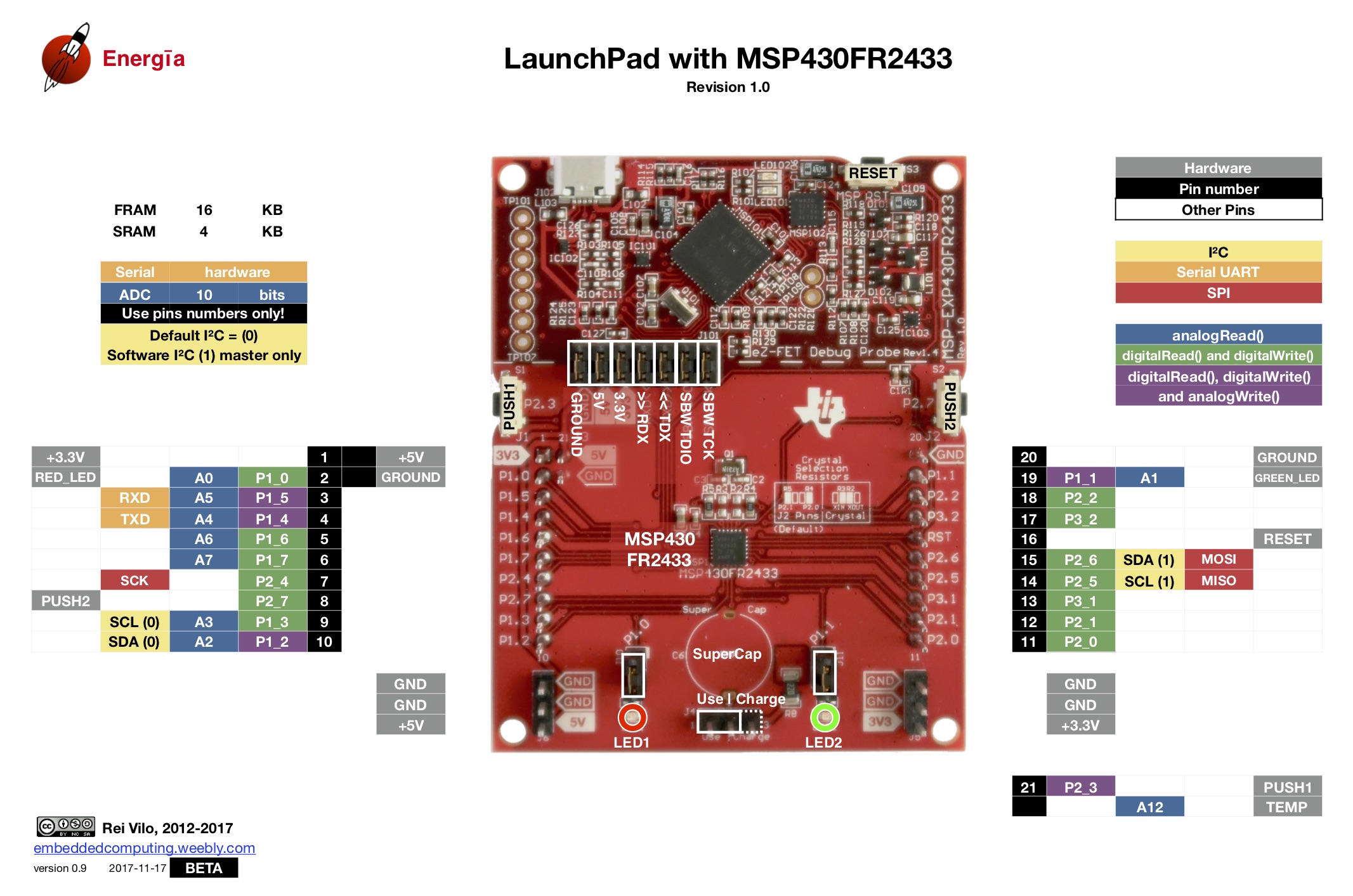
We are working on support in Energia 18 and beyond.
C2000 Piccolo devices are performance MCUs. They are commonly used for real-time control such as motor control, digital power, and dynamic lighting applications, but can be used for a wide variety of projects and tasks. InstaSPIN-FOC technology included with the LAUNCHXL-F28027F LaunchPad makes spinning motors very easy.
The following diagram shows the complete pin map for the C2000 Piccolo F28027 LaunchPad in Energia. Click the image to enlarge.

Energia currently supports the C2000 LaunchPad on Windows and Linux. Due to some licensing restrictions, a few extra steps need to be taken to set up Energia for the C2000 Launchpads.
Download and install Energia 17
Download the C2000 compiler version 6.2.6 from here
Start the installation process by executing the installer. A window with C2000 Code Generation Tools should appear
Continue through the process until the installation directory can be chosen
Change the Installation directory to the \energia\hardware\tools\c2000 by navigating to the tools directory under the hardware folder. Then add \c2000 to the path
Continue to finish the setup If Energia was running when the compiler was installed, Energia may need to be restarted for the C2000 Launchpad to appear.
After the C2000 compiler has been installed in the correct location, Energia can be run and the C2000 Launchpad should appear under the Boards menu.
To enable flash programming the serial boot mode of the F28027 device is used. To configure the device for the serial boot mode, set the S1 switches to UP DOWN DOWN and S4 UP.
Pin numbering for the LaunchPad variant in Energia follows the GPIO numbers of the MCU pins on the LaunchPad (see pin mapping diagram below for details). Example: LED D2 can be turned on with:
pinMode(P0, OUTPUT);
digitalWrite(P0, LOW);
*Note: LOW causes the LEDs to turn on while HIGH causes the LEDs to turn off. In addition, the LEDs will occasionally flicker. This is due to the pins P0-P3 being mapped to LED0-LED3. These pins are set to input initially and therefore may pick up interference from wires, electronics, and even our bodies! Due to the interference, the LEDs may flicker occasionally.
Pins can also be addressed by their alternative names. LED0, LED1, LED2, LED3, MISO, MOSI, PUSH1 and other names in the pin mapping below can be used.
LEDS     SPI     I^2C     SCI/UART     BUTTON
LED0     SCK     SDA     RX           PUSH1
LED1     MOSI    SCL     TX
LED2     MISO
LED3
These alternate names can be used as well to address the pins. Example: LED D2/LED0 can be turned on with:
pinMode(LED0, OUTPUT);
digitalWrite(LED0, LOW);
The C2000 Piccolo F28027* LaunchPad has 4 buttons/switches indicated by an S# next to them. The functions of these buttons/switches are described below.
The Boot Mode Switches are 3 switches which are used to control the mode of the launchpad. When uploading programs with Energia, the boot mode switches should be in SCI/UART mode ( UP DOWN DOWN). This allows the launchpad to communicate with the computer serially.
The table below shows the different boot modes and their configuration.
1 = switched up, 0 = switched down, x = don’t care
S1 |
GPIO34 |
GPIO37 |
TRSTn |
|
Switch |
1 |
2 |
3 |
Function |
Mode EMU |
x |
x |
1 |
Emulation Boot |
Mode 0 |
0 |
0 |
0 |
Parallel I/O |
Mode 1 |
1 |
0 |
0 |
SCI/UART |
Mode 2 |
0 |
1 |
0 |
Wait |
Mode 3 |
1 |
1 |
0 |
GetMode |
The S2 button when pressed will reset the device.
The S3 button when pressed will cause GPIO12 to go high. When not pressed, GPIO12 will be in a low state.
The S4 switch is used to determine if SCI is connected. When on, the board can send and receive serial information. When using Energia, the serial switch should be UP to allow for serial communication.
S4 |
Switch |
OFF |
P28 - J1.3/ P29 - J1.4 |
ON |
P28 - J1.3 - SCI_RX/ P29 - J1.4 - SCI_TX |
The C2000 Launchpad has two separate power domains for the purpose of allowing JTAG isolation. The jumpers on the launchpad configure whether USB power is passed to the target device. The table below contains the possible configurations. If JP1 is not connected, the device can be powered from an external 3.3V source.
Jumper |
Power Domain |
JP1 |
3.3V |
JP2 |
Ground |
JP3 |
5V |