
Learn how to use a shift register to convert serial data to parallel data.
TI LaunchPad
Breadboard BoosterPack
Breadboard
Shift Register (SN74HC595)
4x Red LED
4x Green LED
9x Jumper Wires
8x 330 ohm resistor (optional)
In this example we will use a shift register, a serial to parallel converter, to let us gain more output pins and explore the concept of shifting bits. Bits are the most basic unit of information in electronics. A bit is binary so it contains two values (On/Off, High/Low, 1/0, True/False, etc.). You can link multiple shift registers together to create a large amount of outputs. We will clock data in and then latch it until 8 bits of data have been shifted out.
The shift register is an integrated circuit (IC) which are often called "chips" because of their familiar packaging. You can think of an IC as a much smaller version of a circuit that you could build on your breadboard. ICs help us perform complex analog or digital operations in a small space. That’s how we are able to shrink computers from taking up a whole room to nicely fitting in our pockets and back packs. Not all ICs are the same, in fact they are all quite different. Some, like the microcontroller on your LaunchPad, are very capable and complex, while others like your shift register are relatively simple. One IC might cost a few dollars while another might cost a few cents depending on what functions they can do.
This shift register is very good because it has a DIP package, which means it is breadboard friendly! You can plug in the legs directly to your breadboard along the spine. If you look for ICs to add to your collection later, make sure they are DIP if you want to use them easily with your breadboard.
How do we know how the shift register works? We will use an important guide called a datasheet. A datasheet is provided by the manufacturer of the component. It is the instruction manual. For this shift register SN74HC595, the manufacturer is Texas Instruments and the datasheet is here: http://www.ti.com/lit/ds/symlink/sn74hc595.pdf. You can find datasheets on the product page of most electronic components. If you can’t find it, search around using the part number and "datasheet" keyword.
Your LaunchPad also has a datasheet for the processor that is on board. If you want to learn a lot about how your LaunchPad works, you can study the datasheet! Electrical Engineers need to study datasheets for their components so they can build systems correctly. With Energia, we get spoiled because we don’t always have to read a datasheet to get things working quickly. This is convenient but proper engineering requires knowledge of every aspect of your system, so datasheet knowledge is a must.
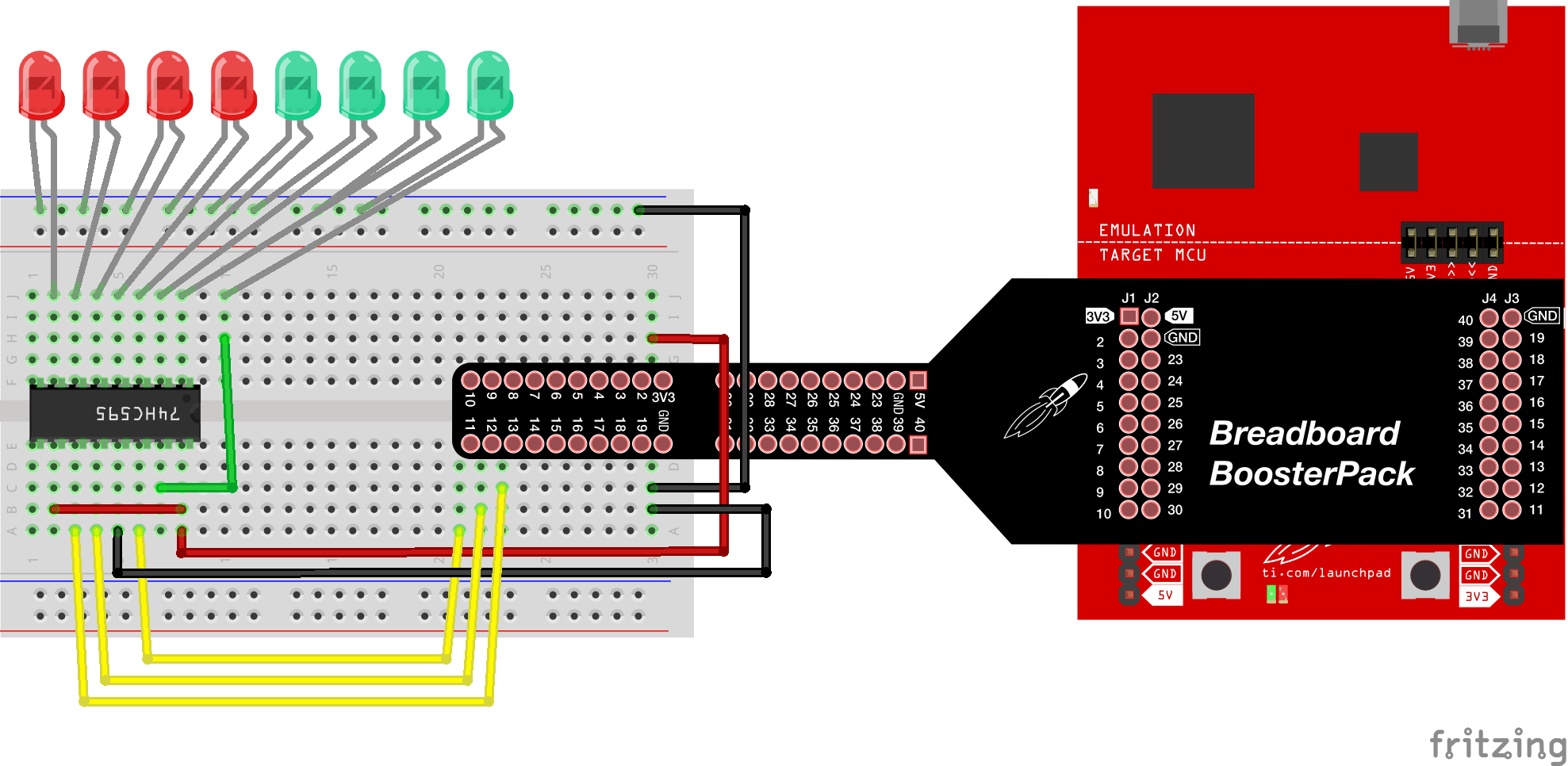
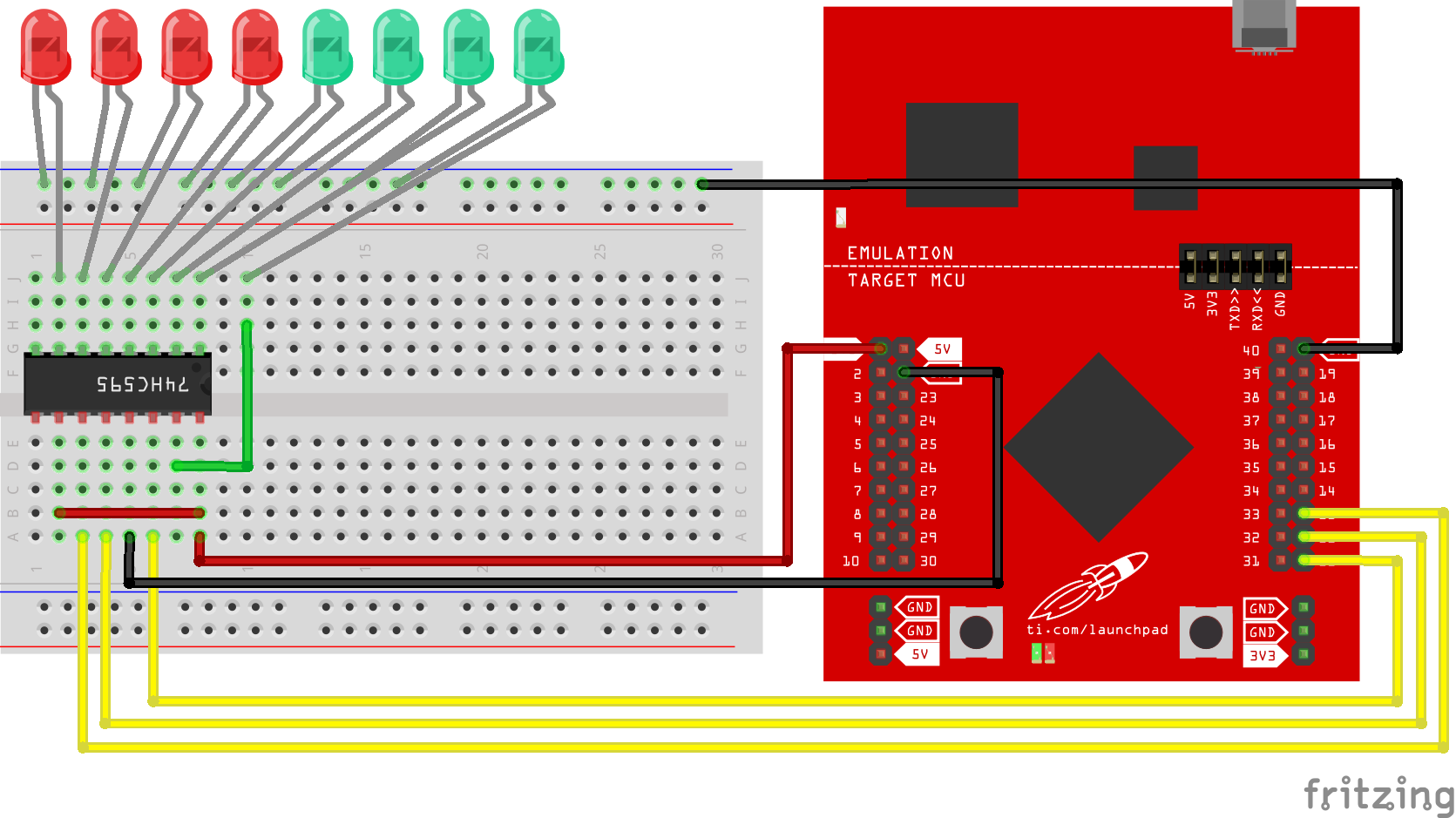
In this example we will make a binary counter using LEDs. The code will let us count up to 256 in binary. Search the internet and learn more about binary counting if it doesn’t make sense how the LEDs are lighting up. Circuit & Schematic
With Breadboard BoosterPack
With LaunchPad
/*
Example 04: Shift Register (Integrated Circuit)
Sidekick Basic Kit for TI LaunchPad
Use a shift register to control multiple LEDs with less pins
SN74HC595: 8-Bit Serial-In, Parallel-Out Shift
Hardware Required:
* TI LaunchPad
* Breadboard BoosterPack
* Breadboard
* Shift Register (SN74HC595)
* 8x LEDs (Green and Red)
* 10x Jumper wires
* 8x 330 ohm resistor (optional)
This example code is in the public domain.
*/
// The SN74HC595 works with a protocol called SPI (Serial Peripheral
// Interface) that uses 3 pins: data, latch, and clock.
int data = 11; // connect data of shift register to pin 11 or LaunchPad
int latch = 12; // connect latch of shift register to pin 12 of LaunchPad
int clock = 13; // connect clock of shift register to pin 13 of LaunchPad
/* Connect the pins of the shift register accordingly
//////////////TOP//////////////
pin 1: LED2 pin 16: VCC
pin 2: LED3 pin 15: LED1
pin 3: LED4 pin 14: data
pin 4: LED5 pin 13: GND
pin 5: LED6 pin 12: latch
pin 6: LED7 pin 11: clock
pin 7: LED8 pin 10: VCC
pin 8: GND pin 9:
////////////BOTTOM/////////////
*/
/* In the setup function we will set our data, clock, and latch pins
* to output. That's all we need to do at setup.
*/
void setup()
{
pinMode(data, OUTPUT);
pinMode(latch, OUTPUT);
pinMode(clock, OUTPUT);
}
/* In the loop section we will call the updateRegister() function defined later
* in the code. There is also another way to do it using updateRegister2().
* We use both to show that the result is the same.
*/
void loop()
{
int delayTime = 300; // the number of milliseconds to delay between LED updates
for(int i = 0; i < 256; i++){
updateRegister(i);
delay(delayTime);
}
for(int i = 0; i < 256; i++){
updateRegister2(i);
delay(delayTime);
}
}
/* updateRegister() - in this function we will update the state of the shift register.
* We first pull the latch pin low, then we use shiftOut() to shift the 8 bits to the
* shift register. Then we pull the latch pin high to display the new bits.
*/
void updateRegister(int value){
digitalWrite(latch, LOW);
shiftOut(data, clock, MSBFIRST, value);
digitalWrite(latch, HIGH);
}
/* updateRegister2() - in this function we will update the state of the shift register.
* We first pull the latch pin low, then for each bit we use a bit mask to check bit by
* bit which LEDs should be illuminated based on which number we are writing. This bit
* mask uses the binary 'and' operation to compare the value being written with the bit
* mask equal to '10000000'. If the most significant bit, or the left-most bit, is a
* '1', then the result of the 'and' operation will also be a '1'. We then shift the
* data stored in the value variable left by one bit so that every bit will sequentially
* become the most significant bit. A shift is done using the '<<' operator to shift the
* value left, or the '>>' operator to shift the value right. If the most significant bit
* is determined to be a '1', then the corresponding LED is illuminated by writing HIGH to
* the data pin, otherwise a LOW is written. Iterating through the value eight times allows
* each bit to be compared to the bit mask. After this comparison on all eight bits is
* complete, we pulse the clock by turning it HIGH then LOW very quickly. We then pull the
* latch pin high to display the new bits.
*/
void updateRegister2(int value){
digitalWrite(latch, LOW);
for(int i = 0; i < 8; i++){ // Repeat 8 times (once for each bit)
int bit = value & B10000000; // bitmask
value = value << 1; // Move up one bit value
if(bit == 128) {
digitalWrite(data, HIGH); // if last bit is set, pull data pin high
} else {
digitalWrite(data, LOW); // if last bit is unset, pull data pin low
}
digitalWrite(clock, HIGH); // pulse the clock pin
delay(1);
digitalWrite(clock, LOW);
}
digitalWrite(latch, HIGH);
}Programming Challenge
Can you get the LEDs to light up in sequences? Check Example 3 for a reminder on different patterns.
Can you control a 7 Segment Display with the Shift Register? Check Example 10 to learn about the 7 Segment Display. Troubleshooting
Code not uploading?
Check for errors in Energia debug window. The compiler will tell you what is happening. Errors are in red text.
Sometimes your LaunchPad gets stuck or hung up on the previous code. Unplug your LaunchPad and plug it back in to perform a full reset. This is called a power on reset. Sometimes using the RESET button can work but taking away the power and letting the microcontroller fully reset is often best.
If you have a failure to upload it could be your drivers are not properly installed. Energia will sometimes give the error "No unused FET Found" which means it can’t find a LaunchPad connected to your computer. Make sure you download the drivers for your operating system found on the Getting Started Guide.
If you had no problem with the previous Blink example, your Energia should be correctly set up. Restart your LaunchPad and restart Energia IDE if you encounter any problems. Make sure to select the right serial port and board type under the Tools menu.
Not working?
Double check your chip is not plugged in backwards. Use the u-shaped notch as a reference point for the top.
LED not lighting up?
Make sure you properly uploaded the code and that you properly named your variables for the LED pins. There is very little chance that your LED is broken, but we can verify by blinking a different LED with the same code.
Make sure your pins are properly connected, if they are not the LED will not light up properly. The GND pin of the LED should be connected to the GND pin of the LaunchPad.
For additional support, try searching the Energia forums on 43oh.com. We believe in you to figure out any problems, now believe in yourself and find the solution!
Corrections, suggestions, and new documentation are very welcomed. They can be contributed to the energia website repository on Github.
The text of the Energia getting started and reference guides are licensed under a Creative Commons Attribution-ShareAlike 3.0 License. The Energia reference is based on the Wiring/Arduino reference. Code samples in the guide are released into the public domain.
Energia sketches are C/C++ based and compiled with the open-source compiler MSPGCC or arm-gcc-none-eabi. The Energia language comes from Wiring. The Energia environment is based on Processing and includes modifications made by Wiring and Arduino.
© Energia