
We will learn how to tell the difference between light and dark using a photoresistor (also known as LDR or photocell).
TI LaunchPad
Breadboard BoosterPack
Breadboard
Photoresistor
1K or 10K ohm resistor
330 ohm resistor (optional)
5x Jumper Wires
We’ve covered sensing physical inputs from humans using a potentiometer and button, but what about sensing environmental characteristics? We can use a special component called a photoresistor to detect how much light is available. A photoresistor is another variable resistor that changes resistance based on light exposure. This won’t be super accurate in measuring light with precision but it can give us a basic gauge of how bright or dark the environment is at the moment. When measuring relative light, higher values occur for a well lit setting and lower values occur in darker settings. For example, you may want the lights in house to turn on when it gets dark, and turn off when the sun comes back out. This is called a passive system, meaning no human interaction is required for it to work properly. An active system will require a human to do some work like push a button. Having systems act in a passive manner can make electronics seem like magic. That’s why sensors are so important to many projects and products!
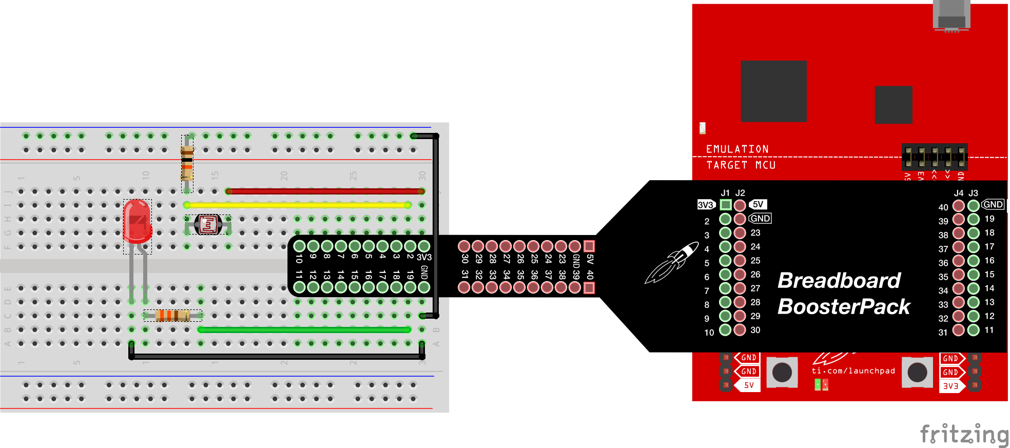
This is a pretty straight forward example on how to use a photocell. Use a voltage divider with a 10K pulldown resistor. If you are in a brighter area, you can use a 1K resistor, which will give you better levels at bright light, but worse detail at darker levels. This is a trade off, depending on what is more important for your project. For this example, we are going to cover the sensor to make a stark contrast between dark and light. Circuit & Schematic
With Breadboard BoosterPack
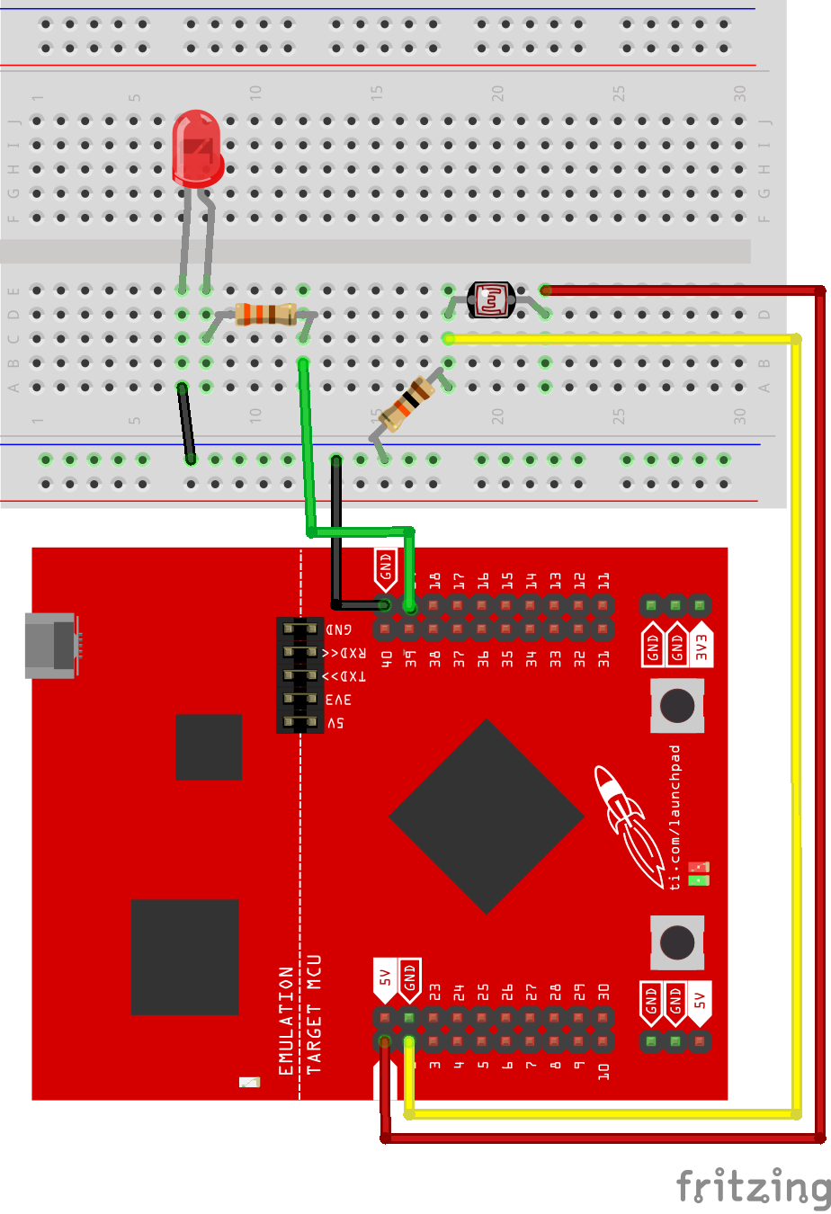
With LaunchPad
/*
  Example 07: Photoresistor (Light Sensor)
  Sidekick Basic Kit for TI LaunchPad

  Use the photoresistor (also called photocell) to trigger a threshold.
  The photocell will change it's resistance based on light. You can
  change the voltage divider to adjust the brightness detected.  The
  photocell is not super sensistive so shine a light and cover it to
  see a significant change. If you are in a lighter room use a 1K ohm
  resistor and use a 10K ohm resistor in a darker room.

  Hardware Required:
  * TI LaunchPad
  * Breadboard
  * Photoresistor
  * Red LED
  * 1K or 10K ohm resistor
  * 330 ohm resistor (optional)
  * 5x Jumper wires

  This example code is in the public domain.
*/


/* In the setup function we initialize serial communication and set
 * the external LED on PWM pin 19 as OUTPUT. You can use a different
 * LED if you prefer. Connect the photoresistor to pin 2.
 */
void setup()
{
  Serial.begin(9600); // initialize serial communication
  pinMode(19, OUTPUT); // sets the LED on pin 19 to output
}

/* In the loop section we will read the photoresistor analog value
 * then we will use the map() and constrain() functions to adjust the
 * range for PWM. When the photoresistor is dark the LED will turn on,
 * you can cover the photoresistor with your hand to block out light.
 */
void loop()
{
  int lightLevel = analogRead(2); // Read the light level from analog pin 2
  delay(1); // delay for 1 millisecond for smoothness
  Serial.println(lightLevel); // Print the analog value to Serial
  // adjust the value 0 to max resolution to span 0 to 255
  lightLevel = map(lightLevel, 0, 4096, 0, 255);
  lightLevel = constrain(lightLevel, 0, 255); // constrain values between 0-255
  analogWrite(19, lightLevel); // Write the PWM value to the LED
}Can you make the LED blink when the photoresistor is covered up and stay on when it is uncovered?
Code not uploading?
Check for errors in Energia debug window. The compiler will tell you what is happening. Errors are in red text.
Sometimes your LaunchPad gets stuck or hung up on the previous code. Unplug your LaunchPad and plug it back in to perform a full reset. This is called a power on reset. Sometimes using the RESET button can work but taking away the power and letting the microcontroller fully reset is often best.
If you have a failure to upload it could be your drivers are not properly installed. Energia will sometimes give the error "No unused FET Found" which means it can’t find a LaunchPad connected to your computer. Make sure you download the drivers for your operating system found on the Getting Started Guide.
If you had no problem with the previous Blink example, your Energia should be correctly set up. Restart your LaunchPad and restart Energia IDE if you encounter any problems. Make sure to select the right serial port and board type under the Tools menu.
LED not lighting up?
Make sure you properly uploaded the code and that you properly named your variables for the LED pins. There is very little chance that your RGB LED is broken, but we can verify by blinking a different LED with the same code.
Make sure your pins are properly connected, if they are not the LED will not light up properly. The GND pin of the LED should be connected to the GND pin of the LaunchPad.
LED not fading?
Make sure you have your 1K or 10K pulldown resistor properly connected. If it is not then the LED won’t fade in a noticeable fashion.
Watch carefully, you may have to completely cover the sensor to notice any changes. Your fading might seem very minor but if it is doing it, then the code is running correctly. You can try to adjust the code to make the effect more dramatic, but the senor is not super sensitive.
You can verify that the sensor is changing by checking your Serial Monitor. You should see the values changing as you interact with the sensor. Make sure your baud rate is set for 9600 and you have selected the correct serial port for UART.
For additional support, try searching the Energia forums on 43oh.com. We believe in you to figure out any problems, now believe in yourself and find the solution!
Corrections, suggestions, and new documentation are very welcomed. They can be contributed to the energia website repository on Github.
The text of the Energia getting started and reference guides are licensed under a Creative Commons Attribution-ShareAlike 3.0 License. The Energia reference is based on the Wiring/Arduino reference. Code samples in the guide are released into the public domain.
Energia sketches are C/C++ based and compiled with the open-source compiler MSPGCC or arm-gcc-none-eabi. The Energia language comes from Wiring. The Energia environment is based on Processing and includes modifications made by Wiring and Arduino.
© Energia