
We will start with a very simple breadboard circuit and learn how to fade an LED with PWM.
TI LaunchPad
Breadboard BoosterPack
Breadboard
RGB LED
4x Jumper Wires
3x 330 ohm resistors (optional)
We are going to continue with LEDs by using a special type called RGB, which stands for Red, Green, Blue. If you know your primary colors, you know that you can make many different colors with combinations of red, green, and blue. RGB LEDs are cool because we can change the color of the same LED, which we can use as an indicator light or for display and decoration. This LED is different because it has four legs instead of two. Three legs are connected to the Red, Green, Blue colors and one is connected to VCC. Check the circuit layout to see the proper orientation.
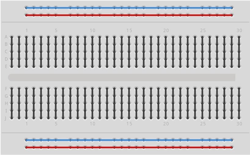
In this example, we are also going to start using the breadboard. A breadboard is a useful tool to help us make circuits without any soldering or other special tools. This is good for prototyping circuits before making custom circuit boards that can make the designs look more clean and compact. A breadboard is laid out in rows and columns that are electrically connected. Simply put a component or wire into one of the holes and it will be electrically connected with anything on the same row. The rows are numbered and labeled so it is easy to share repeatable circuit designs. On the sides are columns called power rails that are indicated with () and (-). The () column is supposed to be connected to VCC which is your voltage source. On the LaunchPad, VCC is 3.3V and should be clearly labeled. The (-) column is supposed to be connected to GND which is your ground signal. GND is always 0V and should be clearly labeled on your LaunchPad.
When we work with electronics there are two primary types of signals: Digital and Analog. A digital signal means it is binary, or has two states: On or Off. We can use the number 1 for ON and number 0 for OFF. It is also common to use the word HIGH for ON and LOW for OFF. So for example we might want to set a digital pin on the LaunchPad HIGH, meaning it is on and electricity is flowing. An analog signal can have a range of value that is not quite fully on or off. For the most part in Energia, we will be dealing with the digital world, but there are times when we will need to interact with analog components, since most of the signals we get in the real world are analog.
A circuit is a system with connections where electricity can freely flow. We will use the breadboard to make simple electrical connections that will help us create projects with different electrical components. In our circuits, the power supply will be the LaunchPad board, which is getting power from the USB cable hooked to your computer.
Pulse Width Modulation, or PWM, is a technique for getting analog results with digital means. Digital control is used to create a square wave, a signal switched between on and off. This on-off pattern can simulate voltages in between full on (~3 Volts) and off (0 Volts) by changing the portion of the time the signal spends on versus the time that the signal spends off. The duration of "on time" is called the pulse width. To get varying analog values, you change, or modulate, that pulse width. If you repeat this on-off pattern fast enough with an LED for example, the result is as if the signal is a steady voltage between 0 and 3v controlling the brightness of the LED.
The analogWrite() function is used for PWM. It requires two arguments: One telling the function which pin to write to, and one indicating what PWM value to write. In order to fade your LED off and on, gradually increase your PWM value from 0 (all the way off) to 255 (all the way on), and then back to 0 once again to complete the cycle. analogWrite() can change the PWM value very fast, so a delay at the end of the sketch can help control the speed of the fade.
When we write Energia code, we are writing in a programming language called C. The C language is decades old but still a very useful language and is common when programming embedded hardware like a microcontroller. Because we are writing in C, we need to follow the C syntax. Syntax is how the code is structured. Just like English or any other language, we need to arrange things in a proper order for it to make sense. An important part of C syntax is making sure you end your lines with a semicolon (;). This tells the compiler when you are finished programming that line. C is a compiled language, meaning it will get processed by the compiler (inside of Energia) and be packaged up into a binary file that can be loaded onto hardware.
Every Energia sketch must contain two main functions. A function is a block of code enclosed with curly brackets. setup() will run at the beginning of the code execution one time. This function is good for initializing things like pinMode() and different library objects like Serial. The loop() function is the code that will run after the setup() function runs one time. The loop() will keep repeating the code inside of the curly brackets forever (or as long as the LaunchPad has power). The parenthesis at the end of the function name, indicates it as a function and sometimes will have variables inside of them that need to be passed to the function.
In code, we have variables, which are things that can store data. If you are familiar with how computer memory works, the variables that we make are given a piece of the memory (memory allocation) to use to store whatever data we want. In Energia, the most common variable is int (integer). This will store a value with no decimal (whole numbers only). A float variable can hold a decimal point number. A char variable can hold an ASCII character.
We have to declare our variables with what type and name they have. For example if we wanted a place to store a number for your age, we can declare a variable "int age;" and if we wanted age to be equal to 15 we can also say that in the declaration "int age = 15;" int is the type, age is the name. Functions also have a type and need to be declared. You will notice that setup() and loop() are type void. Void means it does not return anything, so we don’t need to store anything in memory. A function could return an integer, so we would need to declare it as an int, or it could return a character, so we would need to declare it as a char.
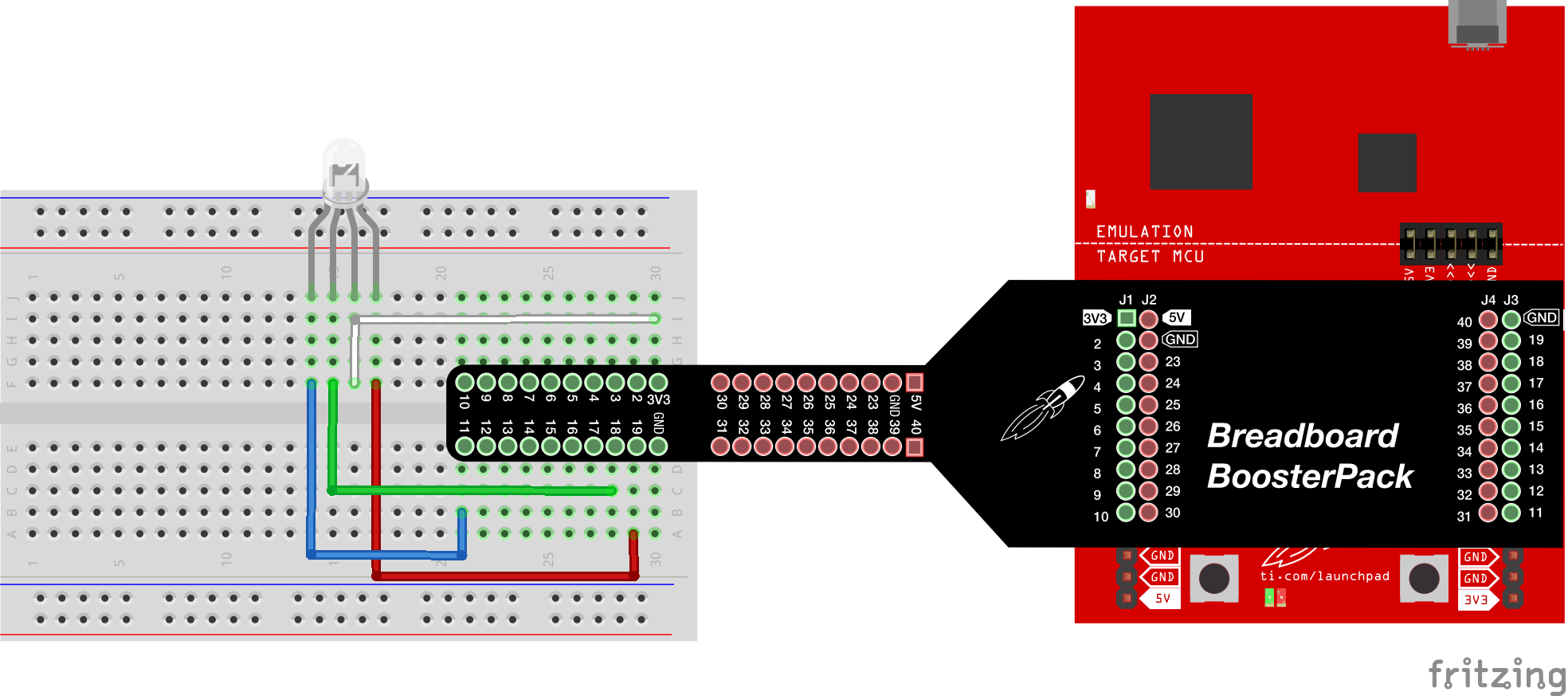
With Breadboard BoosterPack
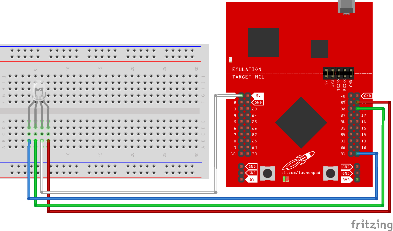
With LaunchPad
Find the latest and greatest code example HERE on GitHub.
/*
 Example 01: Fade RGB LED (PWM)
 Sidekick Basic Kit for TI LaunchPad

 Now we are going to use the special tricolor LED. RGB stands for
 Red, Green, and Blue which are primary colors that can make any
 color we want. This LED can help us make different colors that
 can mean different things.

 We are going to use Pulse Width Modulation to let the LED fade.
 Certain pins on the LaunchPad are PWM capable. In Energia, we call
 this analogWrite() capable. We will want to use those to connect
 to our LED. If you are not sure, check the Energia pin maps on
 the website for your LaunchPad.

 Hardware Required:
 * TI LaunchPad
 * Breadboard BoosterPack
 * Breadboard
 * RGB LED
 * 4x Jumper Wires
 * 3x 330 ohm resistors (optional)

 This example code is in the public domain.
*/

// Connect Anode pin to VCC
// Connect Red to pin 19 which should be PWM capable
// Connect Green to pin with PWM
// Connect Blue to pin with PWM
// You can put a resistor in between to protect your circuit
// but for low power LEDs it's usually okay to drive directly
// from the LaunchPad.

// Let's use #define to rename our pins from numbers to readable variables
// This is good practice when writing code so it is less confusing to read
#define RED 19 // pin 19 is always PWM capable according to LaunchPad standard
#define GREEN 18 // may need to change this for your LaunchPad
#define BLUE 11 // may need to change this for your LaunchPad
#define delayTime 10 // delay between color changes, 10ms by default

// Here we can introduce some global variables. These variables have a type
// (int) and a name. We can use the variables in any function that comes after
// Global variables are useful because we can save the state of a variable to
// use in later operations and functions.
int redVal;
int greenVal;
int blueVal;

/* This is our setup function. We want to set our LED pins as OUTPUT.
 * We can also set them to HIGH at the beginning.
 */
void setup() {
 // We don't have to use pinMode() when using analogWrite() but it doesn't
 // hurt to use it, especially if we want to call digitalWrite() for the
 // same pin in the same sketch.
 pinMode(RED, OUTPUT);
 pinMode(GREEN, OUTPUT);
 pinMode(BLUE, OUTPUT);

 // Test Red
 digitalWrite(RED, LOW);
 digitalWrite(GREEN, HIGH);
 digitalWrite(BLUE, HIGH);
 delay(500);
 // Test Green
 digitalWrite(RED, HIGH);
 digitalWrite(GREEN, LOW);
 digitalWrite(BLUE, HIGH);
 delay(500);
 // Test Blue
 digitalWrite(RED, HIGH);
 digitalWrite(GREEN, HIGH);
 digitalWrite(BLUE, LOW);
 delay(500);
}

/* In the loop function we will fade the brightness of the RGB LED
 * and simultaneously change the colors.
 */
void loop() {

 // We will use a for loop to change the color gradually
 // This will make it fade instead of instantly change
 // We need to go from 0 to 255. You may need to modify
 // your range depending on your LaunchPad to see a smooth
 // result.
 int PWM_RESOLUTION = 255; // this variable will hold our resolution.


 /* Start with full red */
 int redVal = 0; // zero voltage will give us full color
 int greenVal = PWM_RESOLUTION; // max voltage will give us no color
 int blueVal = PWM_RESOLUTION; // max voltage will give us no color
 analogWrite( RED, redVal );
 analogWrite( GREEN, greenVal );
 analogWrite( BLUE, blueVal );

 /* Fade from red to green */
 for( int i = 0 ; i < PWM_RESOLUTION ; i += 1 ){
 greenVal -= 1;
 redVal += 1;
 analogWrite( RED, redVal ); // set the new red value
 analogWrite( GREEN, greenVal ); // set the new green value

 delay( delayTime ); // wait for how long delay time is
 }

 /* Now full green */
 redVal = PWM_RESOLUTION; // max voltage will give us no color
 greenVal = 0; // zero voltage will give us full color
 blueVal = PWM_RESOLUTION; // max voltage will give us no color
 analogWrite( RED, redVal );
 analogWrite( GREEN, greenVal );
 analogWrite( BLUE, blueVal );

 // again we will use the for loop to change the color gradually
 /* Fade from green to blue */
 for( int i = 0 ; i < PWM_RESOLUTION ; i += 1 ){
 blueVal -= 1;
 greenVal += 1;
 analogWrite( BLUE, blueVal ); // set the new blue value
 analogWrite( GREEN, greenVal ); // set the new green value

 delay( delayTime ); // wait for how long delay time is
 }

 /* Now full blue */
 redVal = PWM_RESOLUTION; // max voltage will give us no color
 greenVal = PWM_RESOLUTION; // max voltage will give us no color
 blueVal = 0; // zero voltage will give us full color
 analogWrite( RED, redVal );
 analogWrite( GREEN, greenVal );
 analogWrite( BLUE, blueVal );

 // again we will use the for loop to change the color gradually
 /* Fade from blue to red */
 for( int i = 0 ; i < PWM_RESOLUTION ; i += 1 ){
 redVal -= 1;
 blueVal += 1;
 analogWrite( RED, redVal ); // set the new red value
 analogWrite( BLUE, blueVal ); // set the new blue value

 delay( delayTime ); // wait for how long delay time is
 }
}Can you change the fade speed? Can you create new fade patterns?
Code not uploading?
Check for errors in Energia debug window. The compiler will tell you what is happening. Errors are in red text. Sometimes your LaunchPad gets stuck or hung up on the previous code. Unplug your LaunchPad and plug it back in to perform a full reset. This is called a power on reset. Sometimes using the RESET button can work but taking away the power and letting the microcontroller fully reset is often best.
If you have a failure to upload it could be your drivers are not properly installed. Energia will sometimes give the error "No unused FET Found" which means it canHt find a LaunchPad connected to your computer. Make sure you download the drivers for your operating system found on the Getting Started Guide.
If you had no problem with the previous Blink example, your Energia should be correctly set up. Restart your LaunchPad and restart Energia IDE if you encounter any problems. Make sure to select the right serial port and board type under the Tools menu.
LED not lighting up?
Make sure you properly uploaded the code and that you properly named your variables for the LED pins. There is very little chance that your RGB LED is broken, but we can verify by blinking a different LED with the same code.
Make sure your pins are properly connected, if they are not the LED will not light up properly. The Anode pin of the LED should be connected to the VCC pin of the LaunchPad.
For additional support, try searching the Energia forums on 43oh.com. We believe in you to figure out any problems, now believe in yourself and find the solution!
Corrections, suggestions, and new documentation are very welcomed. They can be contributed to the energia website repository on Github.
The text of the Energia getting started and reference guides are licensed under a Creative Commons Attribution-ShareAlike 3.0 License. The Energia reference is based on the Wiring/Arduino reference. Code samples in the guide are released into the public domain.
Energia sketches are C/C++ based and compiled with the open-source compiler MSPGCC or arm-gcc-none-eabi. The Energia language comes from Wiring. The Energia environment is based on Processing and includes modifications made by Wiring and Arduino.
© Energia