
This example fades 7 LEDs up and the down, one by one, on an MSP-EXP430G2 LaunchPad.
MSP-EXP430G2 LaunchPad
(7) LEDs
(7) 220 ohm resistors
Hook up wire
Breadboard
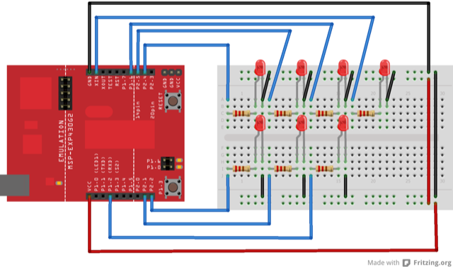
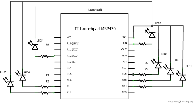
Connect the longer, positive legs of (anodes) 7 LEDs to digital pins 4, 9, 10, 12, 13, 14, 19 through 220 ohm current limiting resistors. Connect the shorter, negative legs (cathodes) to ground.
In the setup() function of the code below, a for() loop is used to assign digital pins 4, 9, 10, 12, 13, 14, 19 of the LaunchPad as outputs.
Next, in the loop() function of the program below, a trio of nested for() loops are used.
The first of these loops,
for (int thisPin =0; analogWritePin[thisPin] <= 7; thisPin++)
moves through each of the LEDS one by one, from the lowest pin to the highest. Before this loop is allowed to move from one pin to the next, two things must be accomplished. First, you brighten the individual LED through these lines of code:
for (int brightness = 0; brightness < 255; brightness++) {
      analogWrite(analogWritePin[thisPin], brightness);
      delay(2);
}
With each pass through the loop above, the variable brightness increases by one point, and that value is written to the pin currently selected to the main loop. One that pin reaches the maximum PWM value (255), the following loop kicks in:
for (int brightness = 255; brightness >= 0; brightness--) {
      analogWrite(analogWritePin[thisPin], brightness);
      delay(2);
}
This loop subtracts a point from the brightness variable, dimming the LED back down to 0. Once zero is reached, the main for() loop kicks in, and the program moves on to the next LED pin, repeating all the steps mentioned above.
/*
  Using all of the analogWrite-capable pins on the LaunchPad!

  This sketch fades LEDs up and down one at a time on digital pins 4, 9, 10, 12, 13, 14, 19.
  This sketch was written for the MSP-EXP430G2 LaunchPad, and leverages the analogWrite capable
  pins on that particular board.
  The circuit:
  * LEDs attached from pins 4, 9, 10, 12, 13, 14, 19 to ground.

  created 8 Feb 2009
  by Tom Igoe

  Modified by Adrian Fernandez on 4/12/2013   This example code is in the public domain.

 */
// These constants won't change.  They're used to give names
// to the pins used:
const int analogWritePin[] = {4, 9, 10, 12, 13, 14, 19};

void setup() {
  // set pins 4, 9, 10, 12, 13, 14, 19 as outputs:
  for (int thisPin =0; thisPin <= 7; thisPin++) {
    pinMode(analogWritePin[thisPin], OUTPUT);
  }
}

void loop() {
  // iterate over the pins:
  for (int thisPin =0; thisPin <= 7; thisPin++) {
    // fade the LED on thisPin from off to brightest:
    for (int brightness = 0; brightness < 255; brightness++) {
      analogWrite(analogWritePin[thisPin], brightness);
      delay(2);
    }
    // fade the LED on thisPin from brithstest to off:
    for (int brightness = 255; brightness >= 0; brightness--) {
      analogWrite(analogWritePin[thisPin], brightness);
      delay(2);
    }
    // pause between LEDs:
    delay(100);
  }
}
Incorporate multiple analog signals into the program.
AnalogInput:use a potentiometer to control the blinking of an LED.
AnalogInOutSerial:read an analog pin, map the result, and use that data to dim or brighten an LED.
Fade:use an analog input to fade an LED.
Calibration:calibrating analog sensor readings.
ForLoop:how to use a for() loop (aka Knight Rider).
Corrections, suggestions, and new documentation are very welcomed. They can be contributed to the energia website repository on Github.
The text of the Energia getting started and reference guides are licensed under a Creative Commons Attribution-ShareAlike 3.0 License. The Energia reference is based on the Wiring/Arduino reference. Code samples in the guide are released into the public domain.
Energia sketches are C/C++ based and compiled with the open-source compiler MSPGCC or arm-gcc-none-eabi. The Energia language comes from Wiring. The Energia environment is based on Processing and includes modifications made by Wiring and Arduino.
© Energia