
This program shows how to blink an LED on the LaunchPad by switching the pushbutton.
MSP-EXP430G2 LaunchPad
Pushbutton [available already on-board as part of the LaunchPad]
LED [available already on-board as a part of the Launchpad]
Momentary button or switch
10K ohm resistor
Breadboard
Hook-up wire
Pushbuttons or switches connect two points in a circuit when you press them. For on-board pushbuttons, the pushbuttons (Pin 1.3) are connected Vcc through PULL-UP resistors. So, when the pushbutton is open (unpressed) there is no connection between the two legs of the pushbutton, so the pin is connected to Vcc(through the pull-up resistor) and reads as HIGH, or 1. When the button is closed (pressed), it makes a connection between its two legs, connecting the pin to ground, so the pin reads as LOW, or 0.
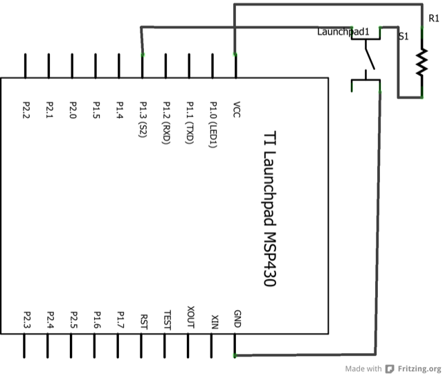
External pushbuttons can be connected either through PULL-UP or PULL-DOWN resistors to any Digital I/0 pins.
Image developed using Fritzing. For more circuit examples, see the Fritzing project page.
For on-board push button
No external circuitry is required.
For external push button
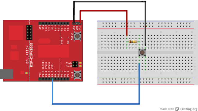
Connect three wires to the Launch pad board. The first two, red and black, connect to the two long vertical rows on the side of the breadboard to provide access to the 3 volt supply and ground. The third wire goes from digital pin p1.3 to one leg of the pushbutton. That same leg of the button connects through a pull-up resistor (here 10 K Ohms) to Vcc. The other leg of the button connects to the ground.
In the program, pin 14, which has green LED connected to it, is set up as output in the setup function.
pinMode(ledPin, OUTPUT);
Here the ledpin refers to the GREEN_LED which is set as output. The push button which is connected to pin 5 is set up as input. The pull-up resistor connected to this pin is enabled.
pinMode(buttonPin, INPUT_PULLUP);
In the main loop, the state of the push button is read to check if it is pressed or not. The state of the pushbutton is read into variable buttonState.
buttonState = digitalRead(buttonPin);
If the buttonState is HIGH, it means that push button was pressed else it is not. Whenever the button state is HIGH, the Green LED is accordingly switched ON else it is switched OFF.
/* Turns on and off a light emitting diode(LED) connected to digital pin 14,
   when pressing a pushbutton attached to pin 2.
  The circuit:
  * LED attached from pin 14 to ground
  * pushbutton attached to pin 5 from ~3V
  * 10K resistor attached to pin 5 from ground

  created 2005
  by DojoDave
  modified 30 Aug 2011
  by Tom Igoe
  modified Apr 27 2012
  by Robert Wessels
*/

const int buttonPin = PUSH2;     // the number of the pushbutton pin
const int ledPin =  GREEN_LED;      // the number of the LED pin
int buttonState = 0;         // variable for reading the pushbutton status
void setup() {
  // initialize the LED pin as an output:
  pinMode(ledPin, OUTPUT);
  // initialize the pushbutton pin as an input:
  pinMode(buttonPin, INPUT_PULLUP);
}
void loop( )
{
  // read the state of the pushbutton value:
  buttonState = digitalRead(buttonPin);
  // check if the pushbutton is pressed.
  // if it is, the button State is HIGH:
  if (buttonState == HIGH)
  {
    // turn LED on:
    digitalWrite(ledPin, HIGH);
  }
  else {
    // turn LED off:
    digitalWrite(ledPin, LOW);
  }
}
Use the button to print something in binary to the serial monitor.
BareMinimum:the bare minimum of code needed to start an Energia sketch.
Blink:turn an LED on and off.
DigitalReadSerial:read a switch, print the state out to the Energia Serial Monitor.
Debounce:read a pushbutton filtering noise.
Button State Change:counting the number of button pushes.
Corrections, suggestions, and new documentation are very welcomed. They can be contributed to the energia website repository on Github.
The text of the Energia getting started and reference guides are licensed under a Creative Commons Attribution-ShareAlike 3.0 License. The Energia reference is based on the Wiring/Arduino reference. Code samples in the guide are released into the public domain.
Energia sketches are C/C++ based and compiled with the open-source compiler MSPGCC or arm-gcc-none-eabi. The Energia language comes from Wiring. The Energia environment is based on Processing and includes modifications made by Wiring and Arduino.
© Energia